Environment, Green Sand, Sand reclamation, Environmental sand reclamation
Sand regeneration unit
Thermal sand preparation


Benefits
- No pit required
- Reduced Nox emissions
- Environmentally friendly
- Compact design
- Reduced gas consumption
Core features
- Smart gas usage
- Efficient temperature control
- 30- 35°C exit temperatures
- Industry 4.0 compatible
- CE compliant
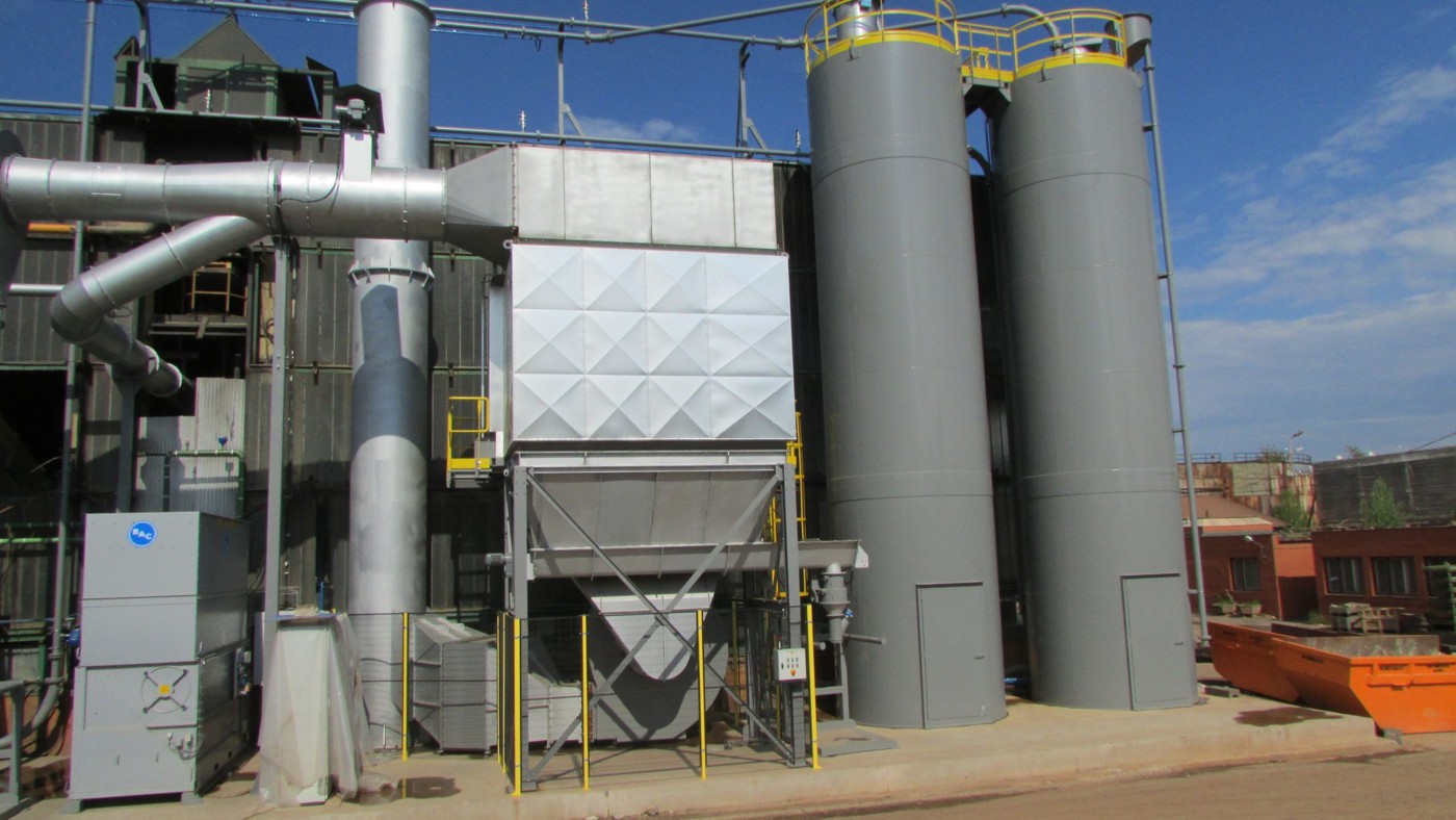
Description
The thermal sand regeneration unit, for chemically bound sand, is an economical solution in more ways than one.
The compact design helps those struggling with their current site layout or capacity.
Secondly, the tower structure for the combustion chamber and sand-cooling unit, means the heat generated from the cooling process reduces the amount of gas required for the combustion process housed in the upper chamber.
Input and output data
- Maintained flow rate – 2T/H
- AFS index – 50 – 55 AFS
- Sand entry temperature – 35°C max
- Entry sand loss – 1%
- Sand exit temperature – 30°C – 35°C
- Sand exit loss – 0.2%
Values based on an input value of maximum 1%
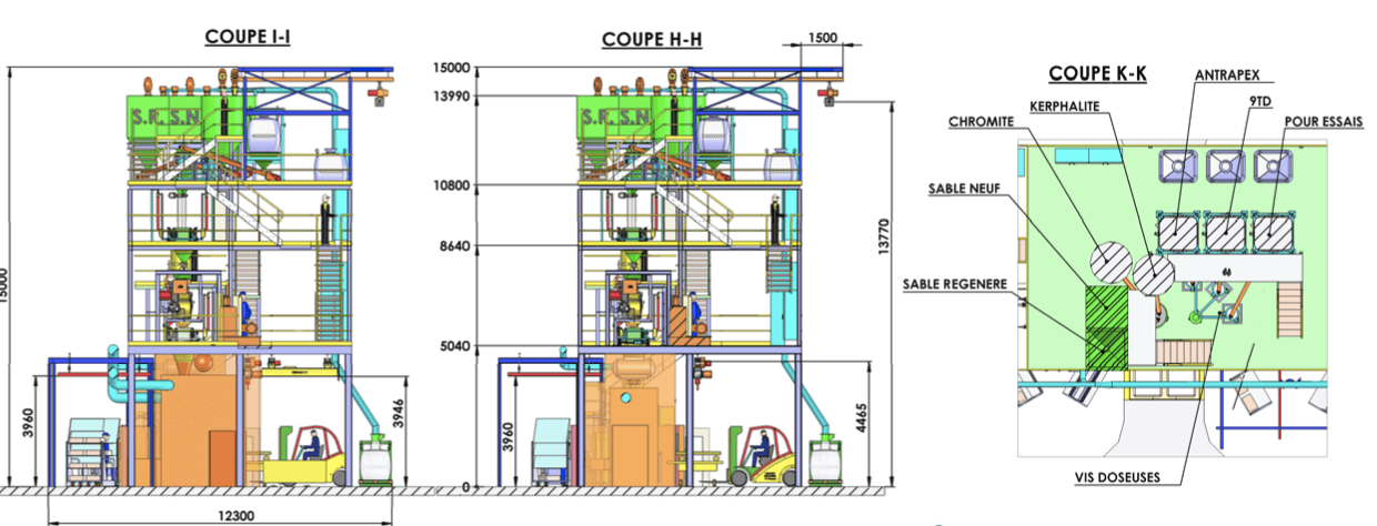
Technical drawings
Technical specs
High performance combustion chamber
The thermal regeneration furnace requires no pit for installation and can support an 8- 9T load on the 4 support structure.
The chamber design avoids any direct contact of the sand reducing burn loss. Complete combustion is achieved allowing for a low Nox emission.
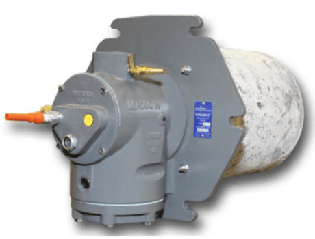
Burner specifications
All chambers are fitted with 2 KINEMAX 3″ Honeywell/Maxon natural gas burners. Each burner produces 704 KW PCS and has a supply pressure of 300 mbar. Both burners are controlled in an independent unit but with an interface on the main control panel.
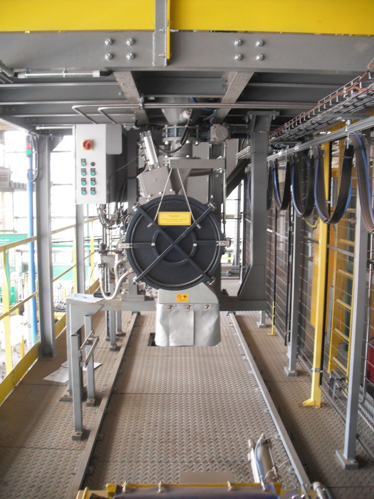
Technical description
The feeding hopper with distribution auger allows a regulated supply of sand into the combustion chamber, held at 650°C. A continual flow of sand is maintained by the fluidizing air. Sand is then transferred by the chute to the cooling chamber where the temperature is reduced by the tubular water exchanger.
Each chamber is equipped with a plate with nozzles, in order to ensure a homogeneous diffusion of the fluidization air over its entire surface.
The key benefits from fluidization air include:
- improved heat exchange in the cooling chamber
- fluid movement of sand in the 2 chambers of the furnace
- reduced gas consumption in the combustion chamber
At the exit of the cooling chamber, a chute equipped with a pneumatically controlled valve is used to supply the downstream. At the top of the furnace, a refractory concrete air casing recovers the combustion gases and dust. Estimated exit temperatures of the air box are 300°C.
The filtration unit, not included standard model, must be equipped with a fresh air flap to reduce the gas temperature to below 180°C at the point of entry to the filter.
Receive the full technical specification and equipment details for Sand regeneration unit as a PDF document direct to your inbox. Simply provide your email and you will receive the download shortly.